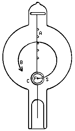
Figure 1: Sectional view of the tube along the B field direction, and filament assembly.
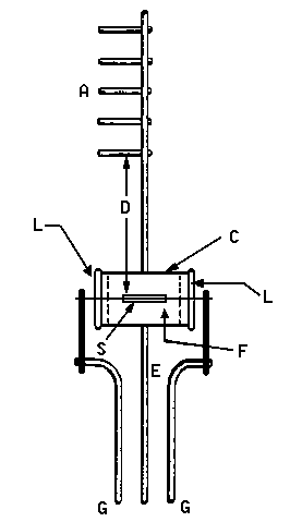
Figure 2: Detailed section of the filament assembly, at right angles to Figure 1.
| PHY 252 | Measurement of e/m for Electrons |
In this experiment you will measure e/m, the ratio of charge e to mass m of the electron. The set-up consists of a visible beam cathode ray tube used to produce a beam of electrons of known energy. The tube contains an electron gun which emits, accelerates, and focuses electrons. For an electron charge e and an accelerating voltage V the (non-relativistic) kinetic energy of the electrons is given by:
K = m v2 / 2 = eV .
The tube is supported at the center of a pair of large Helmholtz coils producing a uniform magnetic field B perpendicular to the velocity of the electrons. Thus, the electrons will be deflected to trace a circular path with a radius determined by e/m, the accelerating voltage V, and the magnetic field B (see equation 1). Helmholtz coils produce a very uniform magnetic field in the region half-way between the coils defined by:
| B = m0N I R2 (R2 + x2)-3/2 , | (1) |
where m0 = 4p×10-7 Henry m-1 is the magnetic permeability of free space, N = 72 is the number of turns on each coil, I the coil current, R the mean radius of the coils, and 2x the distance between coils.
Determine R and x (and their errors!) with a meter stick. Then, for a given coil current I, vary the accelerating voltage V and read off the radius r of the electron orbit. This is done most accurately by tuning the voltage V such that the edge of the beam coincides with one of the five cross bars in the tube. The precise location of the spacebars is given in the Figure. Perform measurements for as many voltage settings as possible, then repeat the sequence for several different current settings. Be careful NOT TO EXCEED the maximum allowed current!
The ratio e/m is given by:
| e / m = 2V (B r)-2 | (2) |
For each I plot V versus B2r2 on graph paper. You should obtain straight lines. Determine e/m from the slope and average over the different values obtained for different values of I. Perform an error analysis estimating your uncertainties in all measured quantities. Compare your final result with the literature value and discuss possible deviations. Derive equations (1) and (2). Discuss how you would improve the precision of the e/m measurement.
Figure 1: Sectional view of the tube along the B field direction, and filament assembly. |
Figure 2: Detailed section of the filament assembly, at right angles to Figure 1. |
| [A] Five cross bars attached to staff wire [B] Typical electron trajectory [C] Cylindrical anode [E] Lead and support wire for anode [F] Filament (cathode) [G] Lead and support wires for filament [L] Insulating plugs [S] Slit in cylindrical anode |
[D] Distances from filament to far side of cross bars:
|
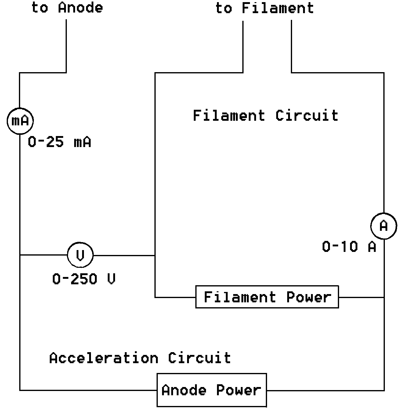 Figure 3: Filament and anode power supply connections. |
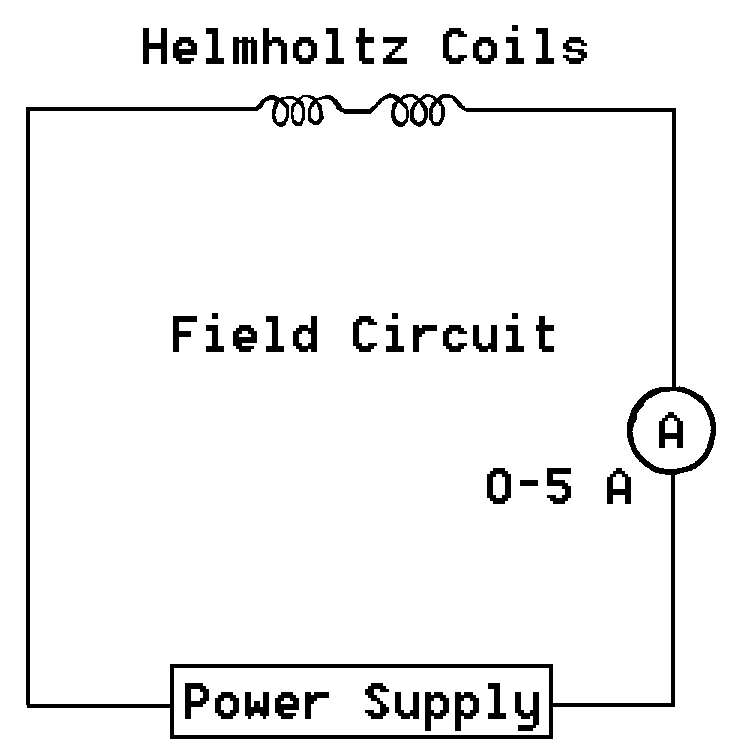 Figure 4: Coil power supply connection. |